
by Haris Dainposh
Metaphorically, the flow of the light inside the fibre can be visualized as a ball bouncing back and forth in a pipeline until it reaches an open end. Both the source and the receiver are coupled to a converter that converts light signals into electronic signals.
An optical fibre or Fibre Optic – usually called the OFC (optical fibre cable) is at the core of the modern communications set up. It has revolutionized everything. It is the key medium that is being used to transfer data.
The OFC
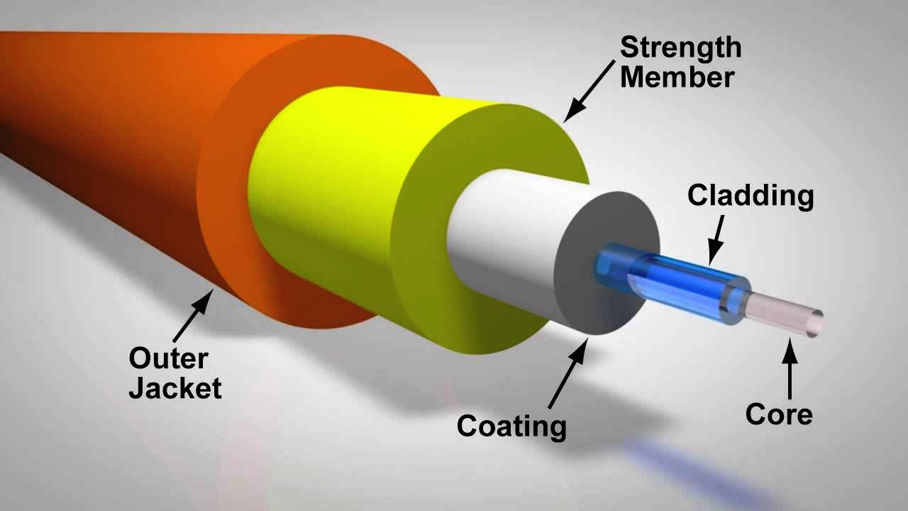
OFC is a transparent flexible wire, made up of just glass, glass plus polymers or just polymers (plastic). The most basic optical fibre consists of Core (an inner cylinder with high refractive index), cladding (a middle cylinder with a low refractive index) and jacket (an outer protective layer).
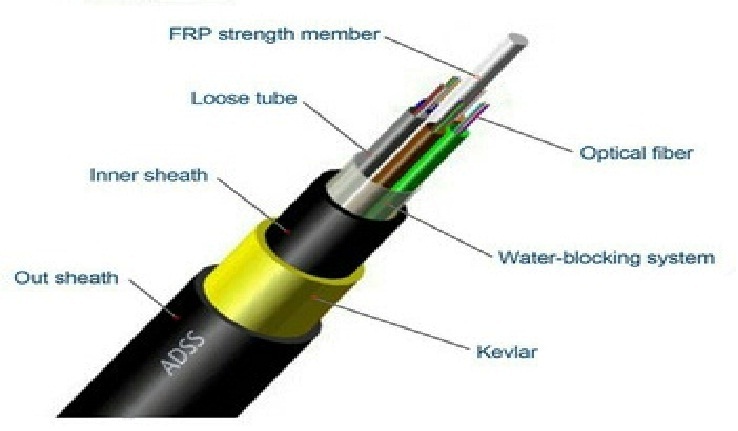
If we see OFC with a bit of interest and observation, we will observe a hard rubber-like covering, jacket (usually polyurethane or PVC). Once we will remove the hard covering, we will see multi-coloured tubes (loose tubes), Central Strength Member (FRP), a Filler and Kevlar Yarns swirled around the tubes. Inside the crevices of these coloured tubes, an OFC can be located.
The tubes are filled with a jelly-like lubricant in order to provide additional protection, block the water from entering inside and blot any external tension on fibre. The tubes can only be removed by smooth proficient handling because the material inside it is quite delicate. As the tubes are stripped open, one notices a bunch of multi-coloured wires, slightly thicker than a human hair, surfaced in a gel-like lubricant.
The numeral categorization of fibres comes up with a colour coding that is layered over both fibre as well as tubes. The colours from one to twelve can be ascended as Blue, Orange, Green, Brown, Grey, White, Red, Black, Yellow, Violet, Pink, and Aqua.
Splicing
What makes these fibres and their inception even more intriguing is that they are jointed through a fusion technique, under which the two fibres are fused by high temperature generated from the electric arc through electrodes inside the machine. The machine is called Splicing Machine and the process is known as Splicing. The entire process is a part of technical handling and it is because of this mode of jointing, that the optical fibre is least prone to the transmission losses, while comparing with the other modes.
 When Data transmission occurs through an optical fibre it employs an optical technology whose main source is a laser and a principle that governs the flow of signals in the medium. It is known as Total Internal Reflection (the complete reflection of a light ray reaching an interface with a less dense medium when the angle of incidence exceeds the critical angle).
Metaphorically, the flow of the light inside the fibre can be visualized as a ball bouncing back and forth in a pipeline until it reaches an open end. Both the source and the receiver are coupled to a converter that converts light signals into electronic signals.
Network Layout
Designing an Optical Fibre is initiated with a survey report to verify the suitable geography for fibre layouts and according to the geographical terrain, the mechanism of the layout is decided. The mechanism of the formation is divided usually into two categories depending on the geographical nature.
If the surface and the inner soil of the area is loose, the projection is carried out by a drilling process known as Horizontal Directional Drilling. But, if the area is inhabited with hard surfaces and imbedded by hard rocks, the process of drilling is replaced by the formation of trenches. It is inside of these drilling holes or open trenches that flexible pipes commonly known as duct pipes (made of UL94/V0 plastic) are pulled out.
Once the development of ducting is completely laid out, the cables are made to pass through these duct pipes avowed by a method of blowing. Once the fibre is blown end to end, the intermediates are joined through the advance of splicing and the endpoints are terminated inside a box known as Fibre Distribution Panel. It is through these distribution panels, that the total loss or a loss at a particular joint can be calculated. This is gradually done by equipment like LSPM (Laser Source Power Meter) or OTDR (Optical Time Domain Reflectometer). Once the fibre is passed over the quality tests, which is governed by the budget loss criteria, the fibre is ready to be used for the data transmission.
OFC, Its Concomitants
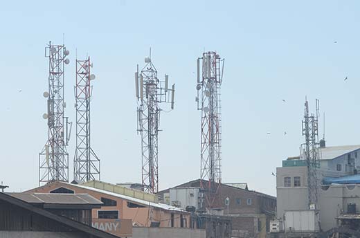
In the anterior years, the main mode of transmission of signals was usually copper cables and later microwave radios. But with the introduction of optical fibre, the usage of both reduced due to a number of drawbacks in comparison with the fibre optics.
Fibre optics possess photonic carriers and photons travel with the speed of light. In copper cables, electronic carriers are used that are inordinately slower in comparison to photonic transmission. It is because of these innards, that the data speed of an OFC is way too faster than a copper cable.

Adjoining the advantages, when travelling over a long distance, fibre optics experience less signal loss than copper cabling known as low attenuation. This gradually increases the quality of media over far-flung remote areas. In addition to this copper cables are more susceptible to electromagnetic interferences and can create a disruption in a network.
Zooming in on the differences, the biggest of all is the bandwidth (the maximum data transfer rate or a network’s capacity which is generally expressed in gigabits per second or megabits per second). It is because of low attenuation and photonic transmission, the bandwidth of OFC is far stronger than the copper cables.
(The author is an engineer who writes when he finds time. He is serving as Network Maintenance Engineer for Bharti Airtel Ltd)


